Stepped Hole ID Measurement System
The system is intended for non-contact scanning and inner diameter measurement of objects having two through-holes of different diameter.
Stepped Hole Inner Diameter Measurement System
| Name of parameter | Value | |
| Measurement range (1st hole), mm | 15...40 | |
| Measurement range (2nd hole), mm | 50...70 | |
| Measurement accuracy, um | ±0,02 | |
| Measurement accuracy, um | ±0,005 | |
| Space resolution (points/turnover) | 6400 | |
| Light source | red semiconductor laser, 660 nm wavelength | |
| Laser output power, mW | <1 | |
| Laser safety Class | 2 (IEC60825-1) | |
| Laser beam shape | Round | |
| Output interface | Ethernet (UDP) | |
| Power supply, V | 9…24 | |
| Power consumption, W | 4 (standby mode), 20 (scan mode) | |
| Environment resistance: | ||
| Enclosure rating | IP67 | |
| Vibration | 20g/10…1000Hz, 6 hours, for each of XYZ axes | |
| Shock | 30 g / 6 ms | |
| Permissible ambient light, lx | 30000 | |
| Relative humidity | 5-95% (no condensation) | |
| Operating ambient temperature, °С | 0…+45 | |
| Storage temperature, °С | -20…+70 | |
| Housing material | aluminum, glass | |
| Weight (without cable), gram | 1500 gram | |
Operation of the internal diameter measurement system is based on the scanning of the hole surface by laser rotation sensors.
The system contains the two stages measuring head with three laser sensors inside, Figure 1.
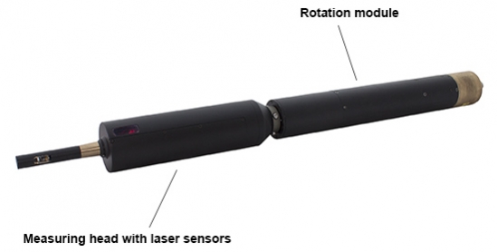

Figure 1. System structure
The first stage is intended for measurement of hole with 15...40 mm diameters and contains one laser sensor (sensor #1 on the figure 1) with measurement range of 6...21 mm from the head axis..
The second stage is intended for measurement of holes with 50...70 mm diameters and contains two laser sensors (sensors #2 and #3) with shifted and overlapped measurement ranges, 24...31 mm and 30...37 mm from head axis.
The measuring head is mounted on the rotation module.
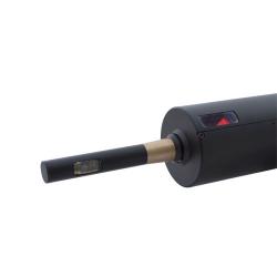
Radiation of a semiconductor lasers from the sensors is focused onto the object surface. Radiation reflected by the surface is collected by input lens of the sensors. Rotating laser sensors scan the inner surface of the object, and the system transmits polar coordinates of the surface (distance from the rotation axis measured by the sensors and a corresponding angle of rotation) to the PC for calculating the required geometric parameters. Overall and mounting dimensions of the system are shown in Figure 2.

Figure 2. Overall and mounting dimensions of the system
Order information for Wheel Center Bore Inner Diameter Measurement System
RF096-D1min/D1max-D2min/D2max
| Symbol | Description |
| D1min/D1max | ID measurement range (1st hole), mm |
| D2min/D2max | ID measurement range (2nd hole), mm |
Example: RF096-15/40-50/70 – Inner Diameter Measurement System For Stepped Holes RF096, measurement range: 15...40 mm (1st hole), 50...70 mm (2nd hole).
Products
Contattaci
Non esitate a contattarci, saremo lieti di soddisfare qualsiasi vostra richiesta di informazione di natura tecnica ed economica,relative alla nostra sensoristica.
Chiedi informazioni